


After selecting CO₂ and pressure, temperature, and humidity compensation sensors, we required a way to interface with the GPIO pins of the compute system. To accomplish this, I designed a custom sensor PCB in a Hardware-Attached-on-Top (HAT) structure that provides mounting for the sensors, and interfaces with the compute system compactly and securely. After receiving fabricated PCBs, I tested, soldered and integrated the sensing PCB along with an active cooler, uninterrupted power supply (UPS), and battery to complete the hardware stack.


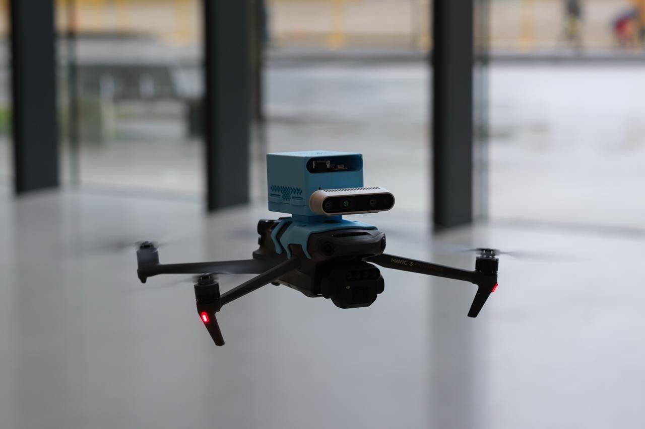
With our field-tests in Taipei and Seoul fast approaching, we were on a significantly accelerated timeline to complete our first iteration. The initial design shown below houses the hardware stack somewhat loosely in a snap-fit enclosure allowing air through the front, which passes across the sensors and hardware and out the bottom vents. A precisely fit bracket fastens the sensing payload to the drone. A stereoscopic camera mount completed the enclosure design. Built hastily to allow for data collection, this initial design was suprisingly robust, if a bit fiddly.
Along with lots of field testing, we spent time at NTU and SNU presenting our project across academic contexts. From small groups to a 40-student graduate seminar, we presented our methodology, design and results, and discussed improvements with local faculty and greenhouse operators. Smart greenhouses equipped with zone-based sensor networks allowed us to effectively validate our measurements and methodology. With tours through engineering labs across both universities, we were lucky enough to learn from students and faculty at two of the top universities in Asia.

A few problems were quickly identified in our field tests in Asia.
The VSLAM algorithm did not respond well to yawing. That is, flying the drone head first and turning at row ends resulted in confusing the localization system. We identified crab-walking as a solution, with hastily-cut vents on the walls of the enclosure to create an omnidirectional intake.
The initial enclosure design lacked a natural airflow path, causing onboard electronics to self-heat under sustained operation. Thermal and CFD analyses were used to characterize internal airflow and identify the root cause.
The hardware stack was somewhat loose in the PCB and was not securely fastened in any way. Additionally, the battery just loose sat under the hardware, rattling during flights and was incredibly annoying to swap as it required prying off the bottom of the enclosure.

I explored multiple enclosure configurations to resolve competing constraints such as structural support for internal components, quick battery access, weight limitation, and a simplified assembly sequence before converging on a final design direction.

I redesigned the enclosure to feature an omnidirectional intake geometry to maintain consistent airflow regardless of flight orientation. Internal components are fastened directly into the enclosure's structure rather than supported by their electrical connectors, improving durability. The electronics stack was also inverted, such that heat rising from the compute system due to buoyancy does not contaminate sensor readings. The active cooler fan draws air through the sensor even while stationary. A tool-free, magnetic quick-swap battery lid completes the design.


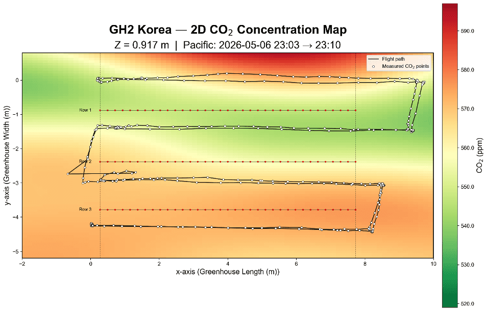
Validation testing is underway, with promising early results when compared to the control stationary ground-station. An academic paper is in preparation showing how aerial sensing can facilitate the creation of digital-twin greenhouses, with me as an author, forecasted for submission for publication in late 2026.


next project
